Locate Visible Faults Quickly
Identify bends, breaks and poorly mated connectors by looking for visible red light escaping from the fiber path.

A Visual Fault Locator sends visible red light through an optical fiber. At sharp bends, breaks or poorly mated connector points, light can escape from the fiber and make the problem visible to the technician.
The VFI4 is intended for quick continuity checks, fiber tracing, splice verification, connector validation and fault finding around fiber cabinets and patching points where OTDR blind spots or dead zones can make very short events difficult to resolve.
High-power AFL VFI4 Visual Fault Identifier.
Low-power AFL VFI4-L Visual Fault Identifier.
Identify bends, breaks and poorly mated connectors by looking for visible red light escaping from the fiber path.
Use the visible source for end-to-end continuity checks and identifying fibers in patch panels or during splicing work.
Use the VFI4 to find short-range faults inside an OTDR dead zone.
The 43 g VFI4 fits in a compact 7.9 × 5.1 × 2.2 cm housing and operates from a single AA battery.
| Feature | VFI4 High Power | VFI4-L Low Power |
|---|---|---|
| Output Power | 5 mW maximum | 1 mW maximum |
| Published Range | Up to 10 km | Up to 4 km |
| Laser Class | Class IIIa (FDA) / Class 3R (IEC 60825-1:2014) | Class II (FDA) / Class 2 (IEC 60825-1:2014) |
| Included Adapters | 2.5 mm + 1.25 mm universal adapters | 2.5 mm universal adapter |
| Battery Life – Flash Mode | <30 hours | <50 hours |
| AFL Part Number | VFI4-01-0900PR | VFI4-02-0900PR |
Identify and trace fibers during activation, installation and patch-panel work.
Perform quick end-to-end continuity verification before more detailed optical testing.
Identify poorly mated connectors and visually validate mechanical connector installations.
Use visible light during splicing operations to help identify fiber paths and gross faults.
Locate visible faults close to connectors or events that may fall inside an OTDR dead zone.
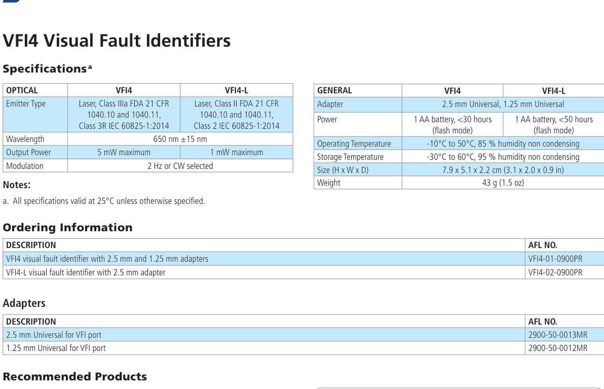
| Parameter | VFI4 | VFI4-L |
|---|---|---|
| Emitter Type | Laser, Class IIIa FDA 21 CFR 1040.10 / 1040.11; Class 3R IEC 60825-1:2014 | Laser, Class II FDA 21 CFR 1040.10 / 1040.11; Class 2 IEC 60825-1:2014 |
| Wavelength | 650 nm ±15 nm | 650 nm ±15 nm |
| Output Power | 5 mW maximum | 1 mW maximum |
| Modulation | 2 Hz or CW selectable | 2 Hz or CW selectable |
| Power | 1 × AA battery; <30 hours flash mode | 1 × AA battery; <50 hours flash mode |
| Operating Temperature | -10°C to +50°C, 85% RH non-condensing | -10°C to +50°C, 85% RH non-condensing |
| Storage Temperature | -30°C to +60°C, 95% RH non-condensing | -30°C to +60°C, 95% RH non-condensing |
| Size (H × W × D) | 7.9 × 5.1 × 2.2 cm | 7.9 × 5.1 × 2.2 cm |
| Weight | 43 g | 43 g |
| Adapter | Use | AFL No. |
|---|---|---|
| 2.5 mm Universal | For VFI port; supports connector formats such as FC, SC and ST | 2900-50-0013MR |
| 1.25 mm Universal | For VFI port; supports LC and MU connector formats | 2900-50-0012MR |
The 1.25 mm universal adapter is included with the VFI4 High Power model only. Verify accessory requirements when specifying the VFI4-L.
| Description | AFL No. |
|---|---|
| VFI4 Visual Fault Identifier with 2.5 mm and 1.25 mm adapters | VFI4-01-0900PR |
| VFI4-L Visual Fault Identifier with 2.5 mm adapter | VFI4-02-0900PR |