Consolidate High Fiber Counts
Use a single multi-fiber trunk assembly instead of routing many individual patch cords through backbone pathways.

Backbone links between data center zones can carry large fiber counts through limited pathways. STAR400 MTP® Trunk Cables combine multiple fiber groups into a pre-terminated assembly, reducing the number of individual cables that must be routed and terminated in the field.
The source positions the family for data centers, high-density environments, storage area networks, communications rooms and data communication networks. Strain-relief hardware and pull-eye installation aids support safer routing and faster mounting into STAR400 products.
Use a single multi-fiber trunk assembly instead of routing many individual patch cords through backbone pathways.
Factory-installed MTP® connectors, fanouts and pull-eye hardware reduce field termination and simplify cable pulling.
Every fiber is supported by IL/RL testing and ferrule-geometry interferometer verification before deployment.
Integrated strain-relief grips are designed for quick cable mounting onto STAR400 products.
The Build Your Order matrix supports an MTP® connector on Side 1 and multiple Side-2 termination choices, allowing the trunk family to support MTP-to-MTP as well as pre-terminated breakout-style assemblies.
Capacity QA: the datasheet states capacity up to 144 fibers, while the Base-8 ordering matrix stops at 12×8 fibers (96 fibers), matching the current website. Confirm the commercial range before publishing a single maximum-fiber claim.
| Parameter | Published Specification |
|---|---|
| Connection Insertion Loss | 0.1 dB typical / 0.3 dB maximum |
| Multimode Loss Variation | ≤0.2 dB after 500 cycles (per EIA-455-21A) |
| Single-Mode Loss Variation | ≤0.3 dB after 500 cycles (per EIA-455-21A) |
| Multimode Fiber Attenuation | <3.0 dB/km @ 850 nm |
| Single-Mode Fiber Attenuation | <0.35 dB/km @ 1310/1550 nm |
| Operating Temperature | -20°C to +70°C |
| Cable Retention | 8 fibers: 400 N; 24-144 fibers: 600 N |
| Connector Retention | 45 N |
| Cable Crush Resistance | 45 N/cm |
| Installation Hardware | Strain-relief grips + pulling-eye material/equipment |
Return Loss QA hold: the source prints “>-35 dB” and “>-60 dB (8° Angle Polish)”. Those values are intentionally withheld from this public table until Engineering confirms the intended notation.
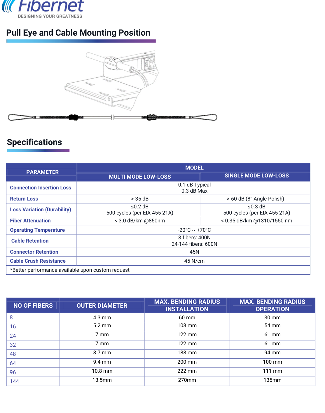
| No. of Fibers | Outer Diameter | Max. Bend Radius – Installation | Max. Bend Radius – Operation |
|---|---|---|---|
| 8 | 4.3 mm | 60 mm | 30 mm |
| 16 | 5.2 mm | 108 mm | 54 mm |
| 24 | 7 mm | 122 mm | 61 mm |
| 32 | 7 mm | 122 mm | 61 mm |
| 48 | 8.7 mm | 188 mm | 94 mm |
| 64 | 9.4 mm | 200 mm | 100 mm |
| 96 | 10.8 mm | 222 mm | 111 mm |
| 144 | 13.5 mm | 270 mm | 135 mm |
The source labels these columns “MAX. BENDING RADIUS”. The values are reproduced as published; engineering should confirm whether the intended term is maximum or minimum bend radius before the table is used in installation instructions.
The supplied datasheet lists the following verification measurements for STAR400 trunk assemblies:
Page 3 also shows a ferrule-geometry interferometer result, reinforcing the documented inspection process for connector geometry.
Pre-terminated high-fiber-count links between racks, rows, distribution areas and equipment zones.
Consolidated fiber pathways where duct and tray space are constrained.
High-density backbone connectivity for storage and compute infrastructure.
Structured trunk cabling between distribution and equipment locations.
Pre-terminated optical backbone deployment in scalable network infrastructure.
Technical QA hold: the source also lists “IEEE 802.3ab-2010 – ETL lab verified (up to 100G Ethernet)”. This claim is intentionally omitted from visible public compliance content pending Fibernet Engineering validation.
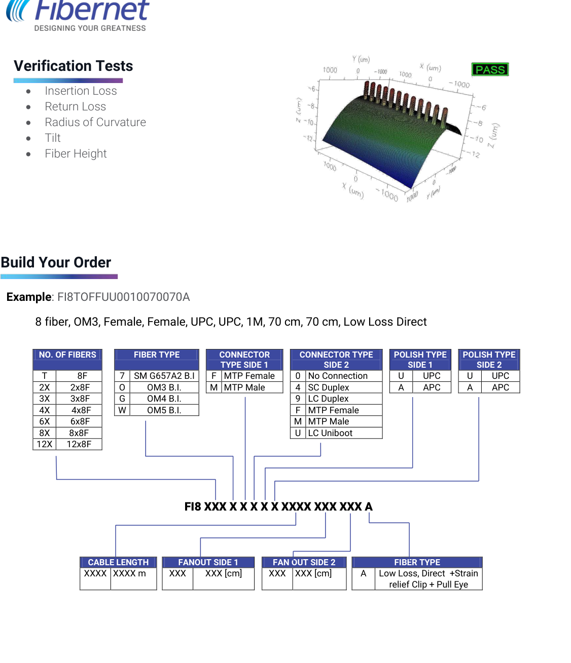
Source ordering pattern: FI8 XXX X X X X X XXXX XXX XXX A
| Selection | Code | Published Options |
|---|---|---|
| No. of Fibers | T / 2X / 3X / 4X / 6X / 8X / 12X | 8F / 2×8F / 3×8F / 4×8F / 6×8F / 8×8F / 12×8F |
| Fiber Type | 7 / O / G / W | 7 = SM G.657A2 BI; O = OM3 BI; G = OM4 BI; W = OM5 BI |
| Connector Type Side 1 | F / M | F = MTP® Female; M = MTP® Male |
| Connector Type Side 2 | 0 / 4 / 9 / F / M / U | 0 = No Connection; 4 = SC Duplex; 9 = LC Duplex; F = MTP® Female; M = MTP® Male; U = LC UniBoot |
| Polish Type Side 1 | U / A | U = UPC; A = APC |
| Polish Type Side 2 | U / A | U = UPC; A = APC |
| Cable Length | XXXX | Length in meters |
| Fanout Side 1 | XXX | Length in cm |
| Fanout Side 2 | XXX | Length in cm |
| Final Code | A | Low Loss, Direct + Strain Relief Clip + Pull Eye |
Published example: FI8TOFFUU0010070070A — 8 fiber, OM3, Female-Female, UPC-UPC, 1 m, 70 cm fanout / 70 cm fanout, Low Loss Direct.