Reduce Cable Congestion
A 2 mm outer diameter and multi-fiber connector format help conserve pathway and patch-panel space in high-density racks.

As data center fiber counts increase, cable bulk can make front-of-rack access and cable management more difficult. Fibernet MTP® Patch Cords use a compact 2 mm cable to provide 8- or 12-fiber connectivity in a small footprint.
The patch cords are pre-terminated with factory-polished MTP® connectors and are available with configurable connector gender, polish, length and polarity. The source positions them for rapid deployment and migration in 40G and 100G data center environments.
**** = length in 0.1 m units; example: 0025 = 2.5 m.
Plug-and-Play 8-fiber MTP® to MTP® optical cable assembly, factory pre-terminated and polished. One 8-fiber MTP® Elite Low Loss Male (pinned) APC connector on each end, Method A polarity, 70 cm breakout legs and SM G.657-A2 9/125 µm bend-insensitive fiber.
**** = length in 0.1 m units; example: 0025 = 2.5 m.
Plug-and-Play 16-fiber MTP® to MTP® optical cable assembly, factory pre-terminated and polished. Two 8-fiber MTP® Elite Low Loss Male (pinned) APC connectors on each end, Method A polarity, 70 cm breakout legs and SM G.657-A2 9/125 µm bend-insensitive fiber.
A 2 mm outer diameter and multi-fiber connector format help conserve pathway and patch-panel space in high-density racks.
Factory-polished MTP® connectors eliminate field connector termination and support repeatable plug-and-play deployment.
Direct and Crossed polarity options support the intended cabling topology, while the datasheet also describes Method-A polarity management.
Each cable can be supplied with individually printed serial numbers, supported by IL/RL and ferrule-geometry testing for every fiber.
OM5 appears in the source standards section, but it does not appear in the supplied Build Your Order matrix. It is therefore not presented here as a standard orderable option.
The source describes the MTP® patch cord as available in either Direct or Crossed polarity and references Method-A polarity management. The Build Your Order matrix also provides separate Direct and Crossed low-loss polarity codes.
For implementation, match the polarity selection to the end-to-end structured cabling design rather than selecting polarity from the patch cord in isolation.
| Parameter | Published Specification |
|---|---|
| Fiber Count | 8 or 12 fibers |
| Multimode Low-Loss Insertion Loss | 0.1 dB typical / 0.35 dB maximum |
| Single-Mode Standard Insertion Loss | 0.25 dB typical / 0.75 dB maximum |
| Loss Variation – Multimode | ≤0.2 dB after 500 cycles (per EIA-455-21A) |
| Loss Variation – Single Mode | ≤0.3 dB after 500 cycles (per EIA-455-21A) |
| Multimode Fiber Attenuation | <3 dB/km @ 850 nm |
| Single-Mode Fiber Attenuation | <0.35 dB/km @ 1310/1550 nm |
| Cable Outer Diameter | 2 mm |
| Bending Radius Limit | 10 mm |
| Operating Temperature | -20°C to +70°C |
| Cable Retention | 100 N |
| Connector Retention | 45 N |
| Cable Crush Resistance | 45 N/cm |
Return Loss QA hold: the supplied source prints “>-35 dB” and “>-60 dB (8° Angle Polish)”. These values are intentionally not repeated in the public spec table until the intended sign notation is confirmed.
High-density patching between MTP® adapter panels, modules, trunks and active equipment.
Multi-fiber connections where cable-space reduction and fast access are important.
Compact pre-terminated fiber links for storage and compute connectivity.
Structured multi-fiber patching in rack-based network infrastructure.
The source identifies high-density Disaster Recovery and Business Continuity sites among field-proven deployments.
Technical QA hold: the source also lists “IEEE 802.3ab-2010 – ETL lab verified (up to 100G Ethernet)”. That claim is intentionally omitted from the public standards list pending Fibernet Engineering review.
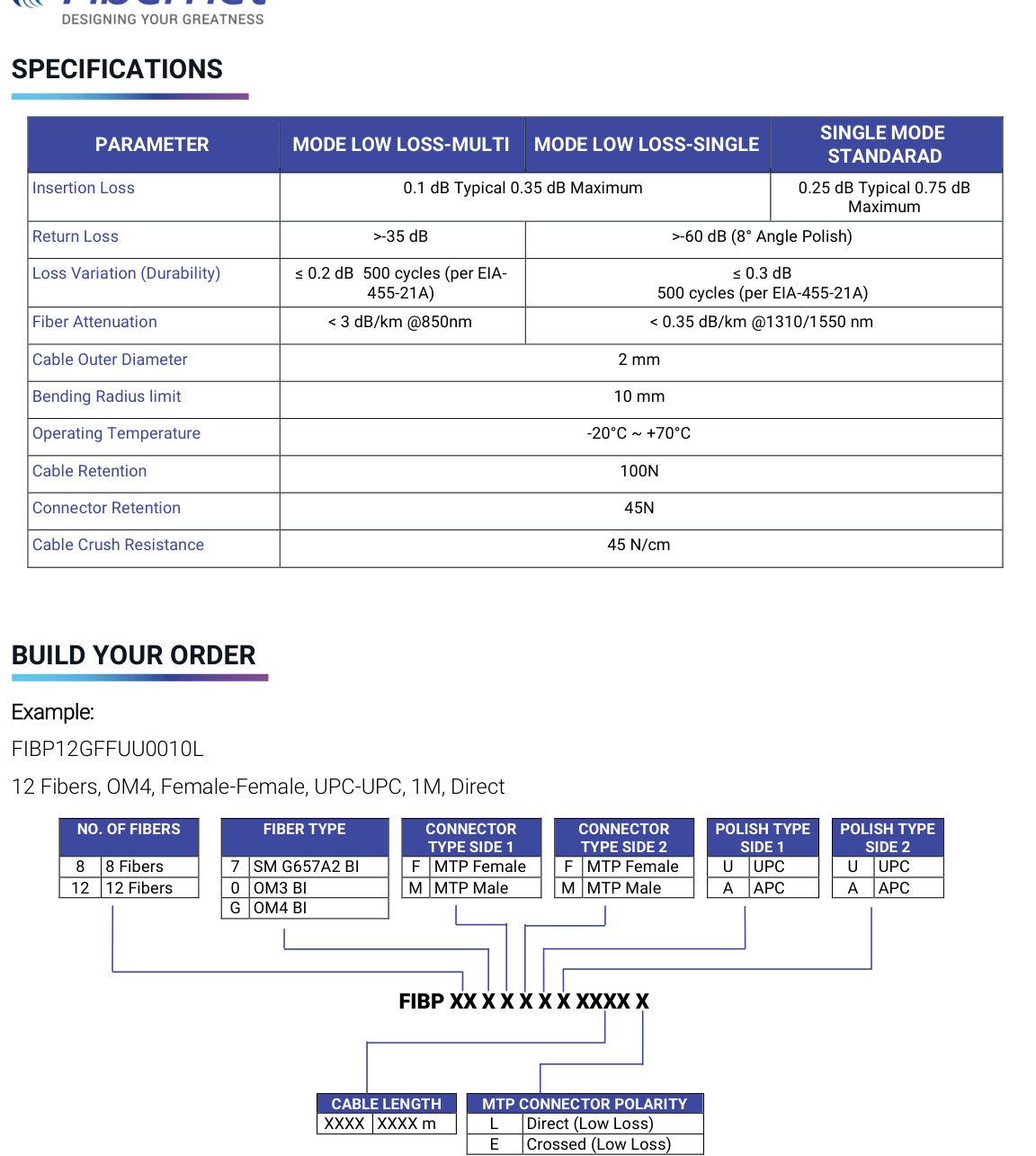
Source ordering pattern: FIBP XX X X X X X XXXX X
| Selection | Code | Published Options |
|---|---|---|
| No. of Fibers | 8 / 12 | 8 fibers / 12 fibers |
| Fiber Type | 7 / 0 / G | 7 = SM G.657A2 BI; 0 = OM3 BI; G = OM4 BI |
| Connector Type Side 1 | F / M | F = MTP® Female; M = MTP® Male |
| Connector Type Side 2 | F / M | F = MTP® Female; M = MTP® Male |
| Polish Type Side 1 | U / A | U = UPC; A = APC |
| Polish Type Side 2 | U / A | U = UPC; A = APC |
| Cable Length | XXXX | Length in meters per ordering code |
| MTP® Connector Polarity | L / E | L = Direct (Low Loss); E = Crossed (Low Loss) |
Published example: FIBP12GFFUU0010L – 12 fibers, OM4, Female-Female, UPC-UPC, 1 m, Direct.