Reduce Patching Congestion
A 2 mm outside diameter helps conserve pathway and rack space in high-density fiber environments.

As rack density increases, patching space and cable-pathway capacity become harder to manage. The Fibernet MTP® Patch Cord packages 8 or 12 fibers into a flexible 2 mm flame-retardant cable, helping reduce cable bulk while maintaining pre-terminated multi-fiber connectivity.
The product is designed for 40 Gb and 100 Gb Ethernet migration in data centers and is available with direct or crossed polarity. On-site reversible polarity provides additional flexibility for moves, adds and changes.
12-Fiber multimode optical patch cord with twelve OM3 50µm Bend-Insensitive fibers in a single jacket. Terminated with 12-fiber MTP® Elite Low Loss connectors: one side Male (pinned), one side Female (unpinned), factory UPC polished, 1 meter in length. Field-reversible polarity allows on-site polarity changes.
12-Fiber multimode optical patch cord with twelve OM3 50µm Bend-Insensitive fibers in a single jacket. Terminated with 12-fiber MTP® Elite Low Loss Male (pinned) connectors on both ends, factory UPC polished, 1 meter in length. Field-reversible polarity allows on-site polarity changes.
A 2 mm outside diameter helps conserve pathway and rack space in high-density fiber environments.
The datasheet positions the patch cord for 10G/40G/100G migration and specifically describes 40G/100G Ethernet data center deployment.
Direct and crossed options, Method A polarity management and on-site reversible polarity support flexible deployment.
IL/RL and interferometer ferrule-geometry testing are performed for every fiber, with individually printed serial numbers for identification.
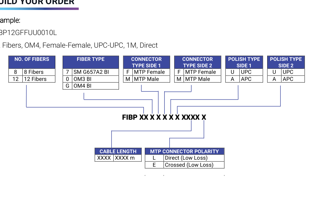
| Option | Published Choices |
|---|---|
| Fiber Count | 8 fibers / 12 fibers |
| Fiber Type | G.657.A2 bend-insensitive single-mode, OM3 B.I., OM4 B.I. |
| Connector Gender – Side 1 | MTP® Female / MTP® Male |
| Connector Gender – Side 2 | MTP® Female / MTP® Male |
| Polish | UPC / APC |
| Polarity | Direct (Low Loss) / Crossed (Low Loss) |
| Cable Length | Custom length via FIBP ordering code |
Ordering example: FIBP12GFFUU0010L — 12 fibers, OM4, Female/Female, UPC/UPC, 1 m, Direct Low Loss.
| Parameter | Published Specification |
|---|---|
| Low-Loss Insertion Loss | 0.1 dB typical; 0.35 dB maximum |
| Single-Mode Standard Insertion Loss | 0.25 dB typical; 0.75 dB maximum |
| Durability / Loss Variation | ≤0.2 dB for multimode low-loss and ≤0.3 dB for single-mode low-loss after 500 cycles (per EIA-455-21A) |
| Fiber Attenuation – Multimode | <3 dB/km @ 850 nm |
| Fiber Attenuation – Single-Mode | <0.35 dB/km @ 1310/1550 nm |
| Cable Outer Diameter | 2 mm |
| Bending Radius Limit | 10 mm |
| Operating Temperature | -20°C to +70°C |
| Cable Retention | 100 N |
| Connector Retention | 45 N |
| Cable Crush Resistance | 45 N/cm |
Pre-terminated 8- and 12-fiber patching for high-density data center links.
Compact 2 mm multi-fiber patching where pathway and rack space are limited.
High-density fiber connectivity for storage-network infrastructure.
Multi-fiber patching between STAR ODF components, panels and network equipment.
The datasheet cites successful use in Disaster Recovery Plan, Business Continuity Planning and central data-center facilities.
The supplied datasheet references the following standards and compliance families: