Monitor Live Fiber Passively
Optical splitter technology creates dedicated Live and TAP outputs for monitoring workflows without requiring an active inline network appliance inside the module.

Network monitoring is most useful when access to traffic is predictable, repeatable and physically integrated into the cabling architecture. STAR400 TAP Modules use optical splitters to create a dedicated monitoring output alongside the live path.
This lets data center teams connect monitoring equipment on demand within the existing STAR400 infrastructure instead of adding a separate external TAP enclosure for each monitored link.
12-fiber SM 9/125 µm TAP module with MTP® input, MTP® TAP connector and four LC Duplex UPC connectors with protective shutters. Optical splitters support the required XX:XX monitoring ratio.
12-fiber SM 9/125 µm TAP module with MTP® input and MTP® TAP connector on the rear and an MTP® connector on the front. Optical splitters support the required XX:XX monitoring ratio.
12-fiber SM 9/125 µm TAP module with an MTP® input on the rear and TAP plus MTP® connectors on the front. Optical splitters support the required XX:XX monitoring ratio.
Optical splitter technology creates dedicated Live and TAP outputs for monitoring workflows without requiring an active inline network appliance inside the module.
Monitoring functionality is integrated into the STAR400 module footprint, reducing the need for a separate monitoring enclosure.
The source positions the module for changing monitored ports without disrupting the live network, helping minimize operational downtime.
LC fibers and ports are individually tested for insertion loss and return loss, numbered for identification and supported by connector ferrule-geometry testing.
| Configuration | TAP Location | Typical Role |
|---|---|---|
| MTP® to 8 LC | Rear TAP connection | Break out monitored paths to individually accessible LC ports. |
| MTP® to MTP® | Rear TAP connection | Maintain multi-fiber MTP® connectivity with rear monitoring access. |
| MTP® to MTP® | Front TAP connection | Maintain multi-fiber connectivity with front-side monitoring access. |
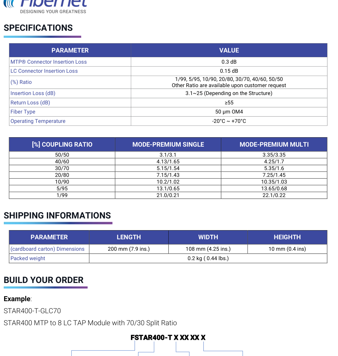
The supplied specification lists multiple optical coupling ratios and states that additional ratios are available on request.
| Published Coupling Ratio | Premium Single Mode Loss (dB) | Premium Multi Mode Loss (dB) |
|---|---|---|
| 50 / 50 | 3.1 / 3.1 | 3.35 / 3.35 |
| 40 / 60 | 4.13 / 1.65 | 4.25 / 1.7 |
| 30 / 70 | 5.15 / 1.54 | 5.35 / 1.6 |
| 20 / 80 | 7.15 / 1.43 | 7.25 / 1.45 |
| 10 / 90 | 10.2 / 1.02 | 10.35 / 1.03 |
| 5 / 95 | 13.1 / 0.65 | 13.65 / 0.68 |
| 1 / 99 | 21.0 / 0.21 | 22.1 / 0.22 |
Ordering QA: the visible matrix is expressed as 50/50 through 1/99, while the source example uses a 70/30 description. Confirm the intended Live/TAP ratio convention before automated SKU generation or ecommerce publication.
| Parameter | Published Specification |
|---|---|
| MTP® Connector Insertion Loss | 0.3 dB |
| LC Connector Insertion Loss | 0.15 dB |
| Coupling Ratios | 1/99, 5/95, 10/90, 20/80, 30/70, 40/60, 50/50; other ratios on request |
| Module Insertion Loss Range | 3.1 to 25 dB depending on structure |
| Return Loss | ≥55 dB |
| Published Fiber Type | 50 µm OM4 in specification table |
| Ordering Fiber Options | OM3 BI / OM4 BI / OM5 BI / G.657A2 BI |
| Operating Temperature | -20°C to +70°C |
| LC Adapter Safety | Built-in shutters |
| Connector Protection | Dust caps |
| Testing | LC IL/RL testing + ferrule-geometry interferometer testing |
| Shipping Carton | 200 × 108 × 10 mm |
| Packed Weight | 0.2 kg (0.44 lb) |
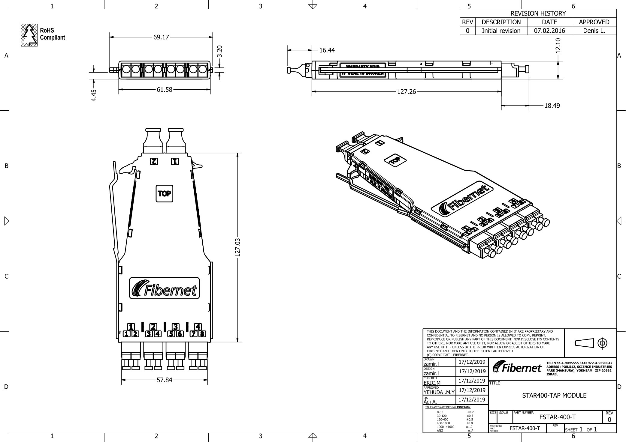
The supplied drawing is titled STAR400-TAP MODULE and identifies P/N FSTAR-400-T. The drawing shows a compact removable module with labeled Live/TAP interfaces and detailed mechanical dimensions.
Download Mechanical Drawing PDF
Provide dedicated optical monitoring paths for production fiber links inside high-density racks.
Feed monitoring platforms with an optical TAP output for visibility into live traffic.
Provide a passive optical feed to approved monitoring or analysis equipment.
Support monitored fiber links in SAN and data communication environments.
Integrate monitoring into modular STAR400 ODF deployments without a separate TAP chassis.
The datasheet also positions the product for 10G Ethernet, parallel optics up to 40G and Fibre Channel up to 16G.
Source ordering pattern: FSTAR400-T X XX XX X
| Selection | Code | Published Options |
|---|---|---|
| Fiber Type | G / O / W / 7 | G = OM3 BI; O = OM4 BI; W = OM5 BI; 7 = G.657A2 BI |
| Adapter in Front | LC / MT | LC = 8 LC; MT = MTP® |
| Split Ratio Live/TAP | 50 / 40 / 30 / 20 / 10 / 5 / 1 | 50/50; 40/60; 30/70; 20/80; 10/90; 5/95; 1/99 |
| TAP Port Location | blank / F | blank = Front; F = Rear |
Published example: STAR400-T-GLC70 — STAR400 MTP to 8 LC TAP Module with 70/30 Split Ratio.